Electrical System Design
The electrical design of our product consisted of a barebone PCB, a 9-DOF sensor, 3 buttons, an OLED screen, a Li-Ion battery, and the Adafruit ESP8266 Huzzah microcontroller. Since we were trying to design a wearable, our main objective was to get as small as form factor as we could and fit all the components snuggly. This can be especially challenging with a small budget and only off the counter general products. Nevertheless, by placing the OLED screen on top of the microcontroller and bringing in the other parts as close as possible we achieved PCD that was 58x50mm.
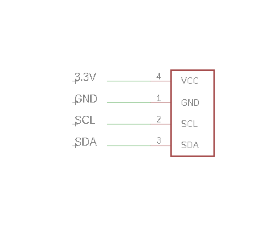
Both the OLED and the 9-DOF sensor communicated to the microcontroller via I2C protocol. Thus they were linked to the same pins on the ESP. Each button was connected to a 10k Ohm resistor and a battery connector was also placed to be surface mounted on the PCB. Since, the appropriate EAGLE Board layout was not found for the 9-DOF sensor, mounting vias were placed on the PCB. For the buttons, a similar solution was developed - pads were placed based on the dimensions of the button contacts.
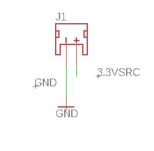
Note that the battery was chosen because the microcontroller can take 3.4V - 6V. The current requirements were also taken into account so that the battery would provide enough to supply all the components.
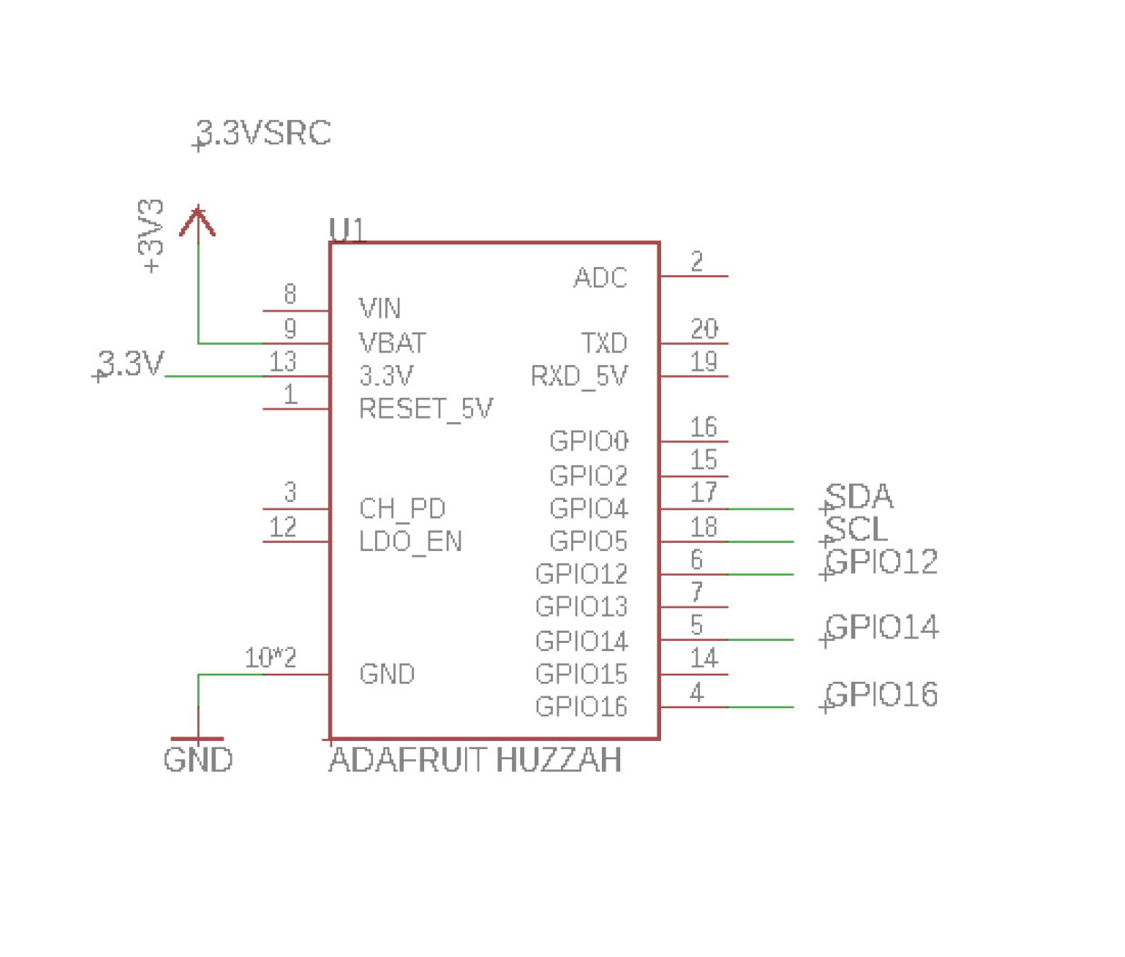
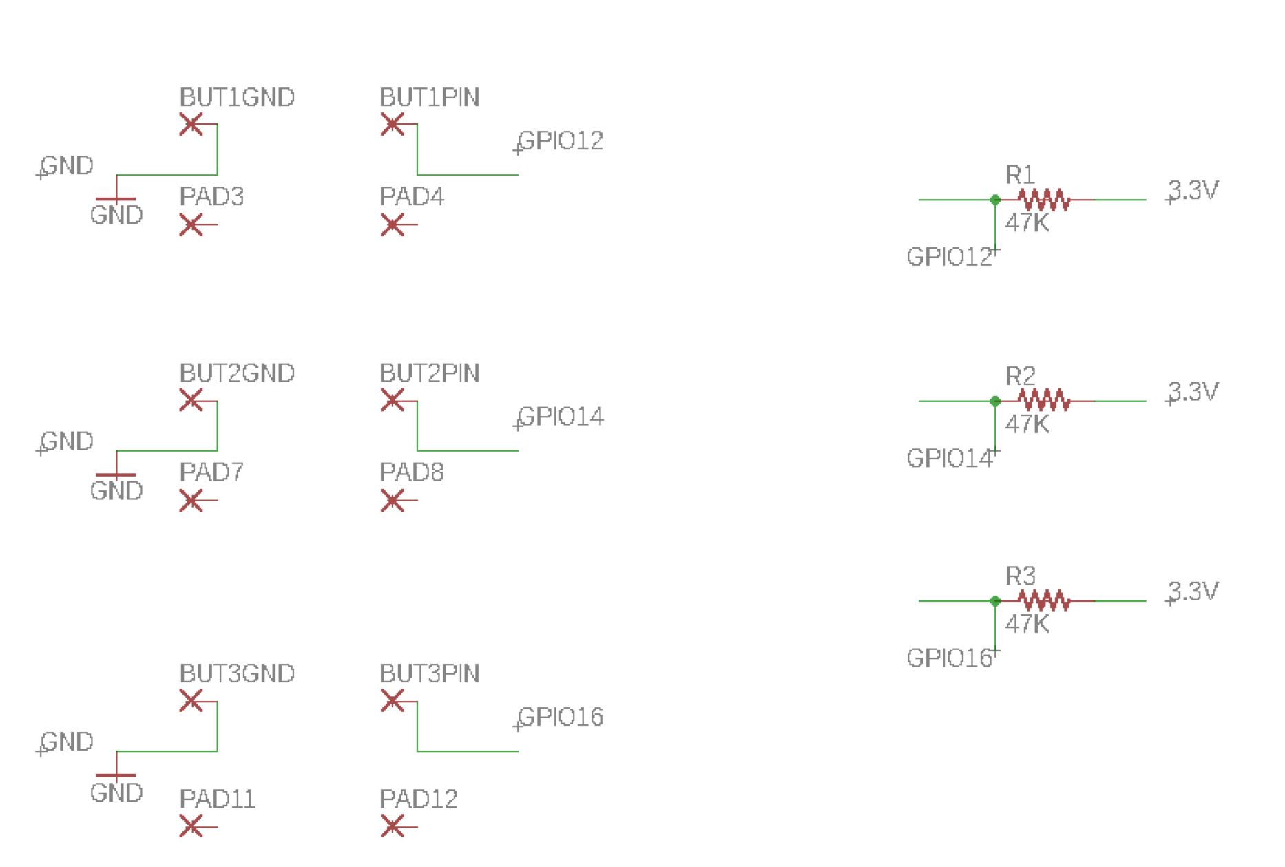
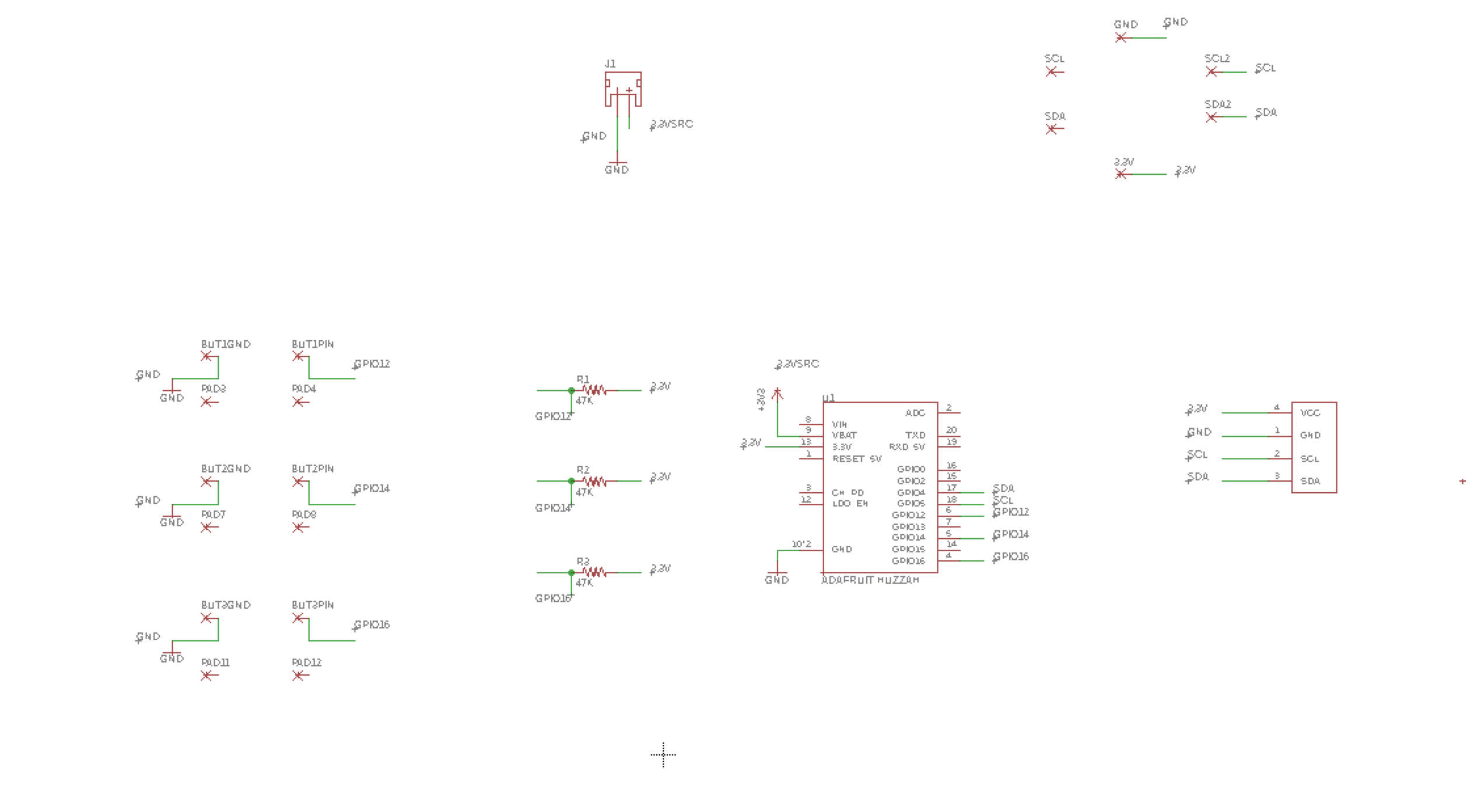
The EAGLE Schematics are provided in the images section. The default I2C SDA and SCL pins (GPIO 4 and 5 respectively) were used for communication. The buttons were linked to GPIO pins 12,14, and 16.
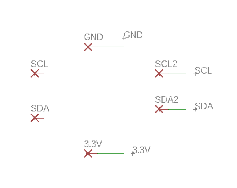
The EAGLE Schematics are broken down so that you can you can see each individual component. The ESP8266 connections, button circuit, 9-DOF connections, battery connections, and OLED connections are depicted separately. There is also a large image depicting the entire PCB together.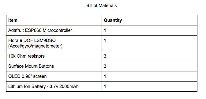
Eagle Schematic Pictures
(ESP 8266, 9 - DOF, OLED, Battery, Buttons, PCB)